Monday, June 10, 2013

Lab 16: Impedance and AC Analysis


 Intro:
The purpose of this lab is to analyze circuits with “real” inductors and the impedance associated with them.

Data:
Determine the inductance.
RL = 10 ohms
Rext= 69 ohms
ω= 2πf= 2π*1000
VIN,RMS=.582V
IIN,RMS=6.3mA
Z=V/I=92.38ohms
L=√(Z2-( RL+ Rext)2  = 7.62mH


Investigating a Series of RLC circuits
c=1/(jω)2 L=3.32μF 
This is too large it should be smaller than 1μF.
For this reason I could not continue.

Lab: 9 Pspice

Intro:
The purpose of this lab is to familiarize my self with the program Pspice for soling complex circuits.
1.

2.

3.


Lab: 8 Freemat


Intro:
The purpose of this lab is an introduction to using the program freemat.


Assignment 1
V1=15V,V2=7V,R1=20ohms,R2=5ohms,R3=10onms
 

The current thought R3 is -.186A
 
Assignment 2
2 2e(-t/τ)  and 2(1-e-t/τ) 


Assignment 3
3 sin(2t + 100) and 3 cos(2t - 300) and at 10Hz


Wednesday, May 22, 2013

Lab 15: Mat Lab Complex Numbers


Intro
We used Matlab to solve a system of equation with complex numbers.


Lab 14: MOSFET Control of an electric motor


Intro:
The purpose of this lab is to set up a mosfet for speed control of a provided motor.


Open Loop Voltage Control Circuit


The Gate Voltage is about 4V.
Turning the pot controls motor voltage because it regulated the voltage into the MOSFET
It is difficut to control the speed because there in not a linear relationship with VGS

PWM Chopper MOSFET


Lab 13: 2nd Order RLC Circuits Lab


Intro:
We used this website
 to learn to solive 2nd order RLC circuits.


Lab 12: Oscilloscope 101


Intro:
The purpose of this lab is to get introduced to using an oscilloscope.

Exercise 1: Displaying and Measuring a Sinusoid

Frequency 5kHz
Period 0.2ms
Peak to peak Amplitude 5V
Zero to peak Amplitude 2.5V
Anticipated RMS = 5/√2
VDC -10.3mV
VAC=1.855mV

Exercise 2: Including a DC Offset
+2.5V DC offset
DC coupling

AC coupling


The difference between them is the ground positioning
VDC = 2.48 mV
VAC = 1.91 mV

Exercise 3: Displaying and Measuring a Square Wave with offset.
VDC = 2.49 mV
VAC = 3.08 mV
RMS= 5V/200μs = 25000


Exercise 4: Measuring Mystery signals


DC voltage 4V
Frequency 67.56 Hz
Pk-Pk Amp .4V

Lab 11: Capacitor Charging/Discharging


Intro:
The purpose of this lab was to observe the charging and discharging of a capacitor.  We built a circuit with a 9V DC power supply that charges 2.5mj for 20s, and discharges in 2s. The time it takes for a capacitor to charge up is 5τ. Where τ = RC. We will model a real storage capacitor with the figure below and find the Thevenin equivalent.

Data:
W=2.5mj         t= 20s              Vs=9

Vcap = Vs(1-e^(5t/τ) = 9.939
C= 2*W/Vcap^2 = 62.57μF

Charging:


20=Rc*C à Rc=64800Ω
I= Vs/Rc= 0.139mA
P=IV=1.25W
Vfinal= 8.87
Vfinal = Rleak / Rc + Rleak à Rleak = 4421353Ω
Charging Process

Discharging:


2=Rd*C à Rd=639.2Ω
I= Vs/Rc= 1.93mA
P=IV=.0125W
Discharging Process

Analysis:
During charging the thevein resistance is found with Vth = Rleak * Rc / (Rc + Rleak) = 63017Ω. During discharging the thevein resistance is 639.1Ω. Vth = Vcap = 9.939V

Lab 10: Op-Amps II


Intro:
The purpose of this lab is to observer the effect of the changing the feedback resisitor on an op-amp circuit with a network of voltages.

Data:

1: 9.80kΩ       RF 94.7Ω
Vin Desired      Vin Actual Vout Measured VRF Measured Iop Calculated
Vin Desired
Vin Actual
Vout Measured
VRF Measured
Iop Calculated
0.25V
0.254V
-2.458V
2.458V
0.01mA
0.5V
0.5V
-4.92V
4.92V
0.01mA
1.0V
0.91V
-9.67V
9.67V
0.01mA
ICC = 1.08 mA              IEE = -0.97 mA


Vin Desired
Vout Measured
VRF Measured
Iop Calculated
ICC Measured
IEE Measured
1.0V
1.0V
-9.07V
0.01mA
1.08 mA
-0.97mA


Analysis:
The since the op-amp was an inverting one the voltage became negative.  The voltage was also amplified by 10 times.  KCL should apply, but our result was a bit off.  ICC + IEE should be 0.  We get 0.11mA.

Lab Op-Amps Extra Credit


Intro:
The purpose of this lab is to use an LM 358 thermal sensor opamp for temperature measurement.  Lm 358 can run 0-5V and can measure 10C  at 10mV.  We want to design an amplification that can measure between 150C to 350C


Analysis:
We were at least come close to room temperature with an error of about two degrees. 
The problem was there were fluctuations of the temperature readings. 

Wednesday, April 10, 2013

Lab 7: Op amps 1


Intro:
The purpose of this lab is to use an operational amplifier to produce an output of 0 to 10 volts, draw no more than 1mA, and supply no more than 30mW of power.

Experiment:


Component      Nominal Value            Measured Value
Rf                     2KΩ                             2.14kΩ
Rf                     2.2KΩ                          2.15KΩΩ
RX                     12KΩ                           11.16KΩ
RY                     100Ω                           98Ω
V1                    12V                              12.28V
V2                    12V                              12.09V

Data:

            VIN        VOUT     GAIN    V­­Ri        IRi                     VRf
            0.0V     0            0          0          0                      0
            0.25V   2.48V   10        .249V   .115mA            .248V
            0.50V   4.97V   10        .500V   .231mA            .500V
            0.75V   7.48V   10        .751V   .348mA            .750V
            1.00V   10.03V 10        1.007V .466mA            1.006V
At VIN = 1.00V 
IV1 = 1.731 mA             IV2 = 1.276 mA

Analysis:
PV1 = V*I=12.2(.001727)= 21.21mW
PV2 = V*I=12.09(.00126)= 15.43mW
The circuit satisfies the power constraint of 30mW. The circuit  can out put 10V with about 1mA of current.

Lab 6: Maximum Power Transfer


Intro:
The purpose of this lab is to experimentally verify the Maxumum Power Transfer Theorem.
P=(Vth /(Rth + RL)2 *RL
Power maximum when Rth = RL
Experiment and Data:
Part A


Data part A


Vo(volts)
Rx(ohms)
Power(mW)
0.015
120
0.001875
0.037
712
0.00192275
0.045
1220
0.00165984
0.069
1890
0.00251905
0.076
2160
0.00267407
0.09
2590
0.00312741
0.117
3590
0.00381309
0.132
4310
0.00404269
0.166
5150
0.00535068
0.165
5730
0.00475131
0.176
6370
0.00486279
0.19
7150
0.00504895
0.219
8940
0.00536477
0.243
10770
0.00548273
0.251
11360
0.00554586

Analysis


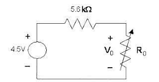
Max power was at around 5.15k ohms.  The theoretical resistance of max power is when the load resistance equals the thevenin resistance.  Since the thevenin resistance is 5.6k ohms the, the load resistance of max power is 5.6k ohms.  The percent error is 8.04%


Part B

We tried to use LoggerPro to find the thevenin resistance, but the program did not work. There was too much noise in the measuring devices.